Enable AWG (signal generator) on a Hantek DSO2C10
December 7, 2022 - Reading time: 6 minutes
Depending on the PCB revision, upgrading the DSO2C1x model of the oscilloscope to enable the function generator can be as simple running some software, or it can involve adding missing components to the board. Guess which one I have?
Missing Hardware
All models of this scope use the same board, with features enabled or disable in software. The "C" models come with the function generator disabled. The first step is to open up the scope and see what your board version is. If you're lucky, you'll find the components already populated and you can skip to the software modding portion! Unfortunately for me I bought an early version of the DSO2C10. I have board revision DSO2D15_V1.0 2020.08.17, and it does not come with the required parts pre-installed.
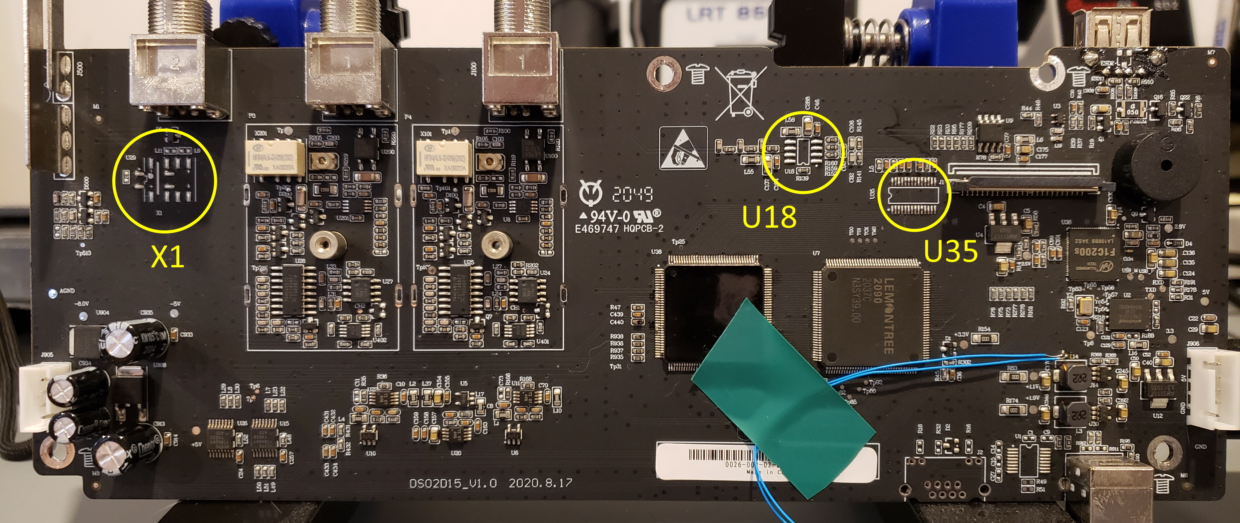
There is a gold mine of information in this massive thread on eevBlog dedicated to hacking this scope. There's a lot to go through, but I found a list of missing parts courtesy of user Boyeen. The parts we're looking for are:
| Relay | X1 | HFD4/4.5-S |
| Op amp | U18 | LMH6702MA |
| DAC | U35 | DAC902E |
I sourced the my parts from Digikey, but you may find them cheaper elsewhere. I should note that it's probably cheaper to buy the DSO2D10 with everything enabled to begin with. At the time of purchase the 2D10's were out of stock, and I wasn't that concerned about the missing function generator.
I couldn't find the relay on Digikey, although it was available on eBay and Aliexpress. I am impatient so I checked the specs and looked for the closest match I could find. The IM02GR (PB1089CT-ND on Digikey) matched the ratings and form factor.
Adding the components isn't too hard, the board isn't densely populated so there's lots of room to maneuver. It definitely helps to remove the board first. The biggest challenge is the DAC, with a pin pitch of 0.65mm. I found the "carry" method worked really well, ymmv.


Software mods and calibration
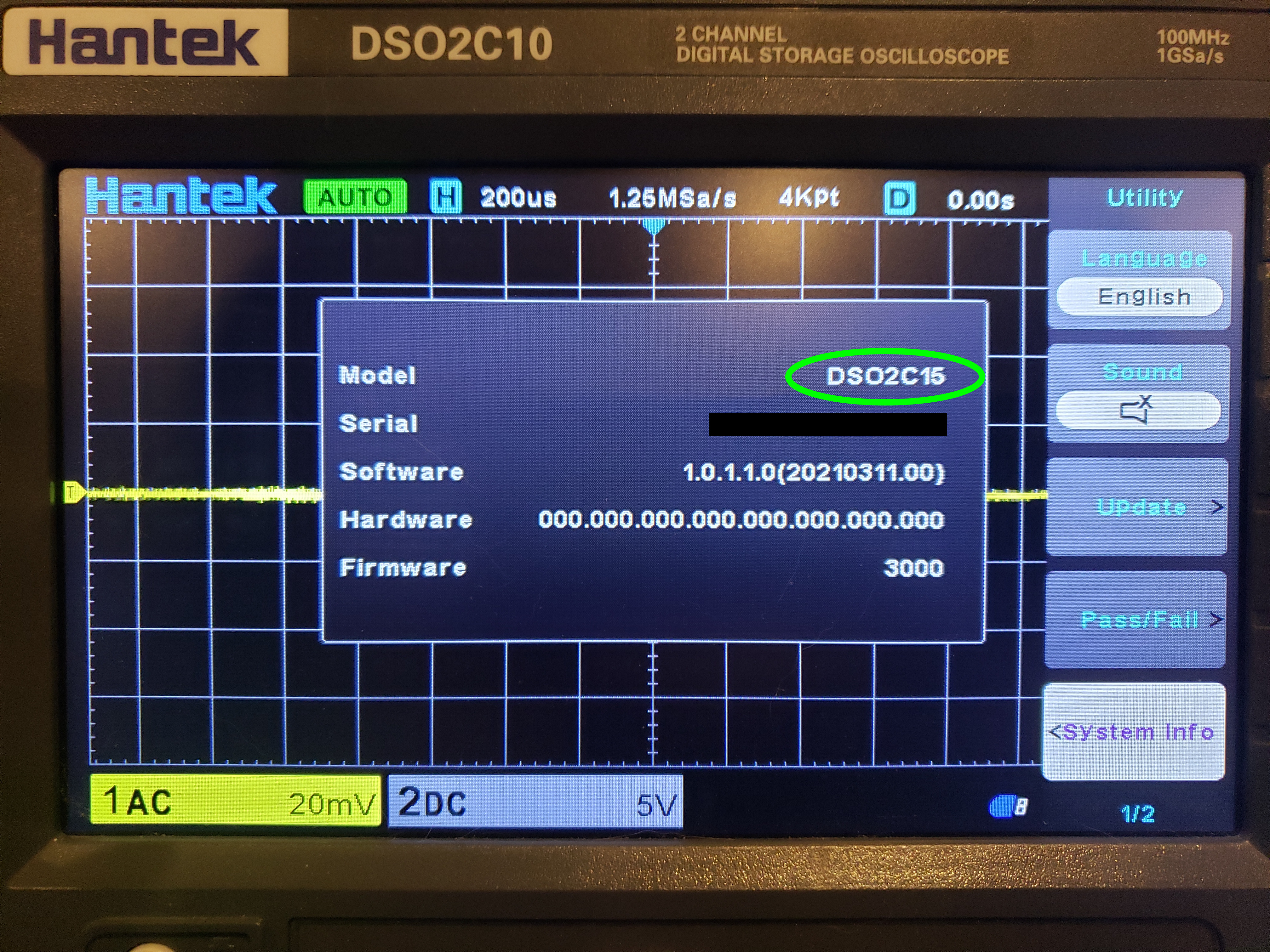
Next we need to tell the scope that it is now a model 2D15. This is done by simple changing the model in two config files:
/cache/system.inf/dso/app/sys_inf.new
The firmware check these files at start up to set the model, and thus the enabled functions.There are multiple ways to go about doing this, but the easiest has been provided for us by user DavidAlfa, also of the eevBlog forums. He has amassed a ton of information and made tools available to everyone via his eevBlog posts as well as a Google Drive full of interesting mods. I have stuck some links down at the bottom if you're interested.
First we need to download the file dso3kb_2D15_conversion.upk from the Mods/2D15_conversion folder on David's google drive. I'll also link a copy below for archival purposes. We need to calibrate the generator too, so grab dso3kb_calibrate_gen.upk from Mods/Generator_Calibration, and while we're at it get dso3kb_backup_builder.upk from Mods/Backup_Builder as well. This will hopefully save us if things go horribly wrong.
Copy all three files to a USB key and plug it into the scope. These files are run just like firmware updates, so we can press Utility, F3 for update, then F1 for the file menu. Turn the menu knob (V0) and click to select. I'd recommend running dso3kb_backup_builder.upk first. When that's done, run dso3kb_2D15_conversion.upk. After the scope reboots, you should see a new addition to the display!
Press the Wave Gen button to enable/disable or bring up the menu. Use the F buttons to select and the menu knob to adjust the value. Here are the instructions for dso3kb_calibrate_gen.upk from David:
This package will calibrate the internal signal generator.
Before proceeding, it's strongly recommended to make a backup using Backup Builder and EEPROM Backup tools!
This package works in two stages:
- First pass: Ensure there's no file named "cal_values" in the usb drive.
Run the package, it will reset the existing calibration and reboot.
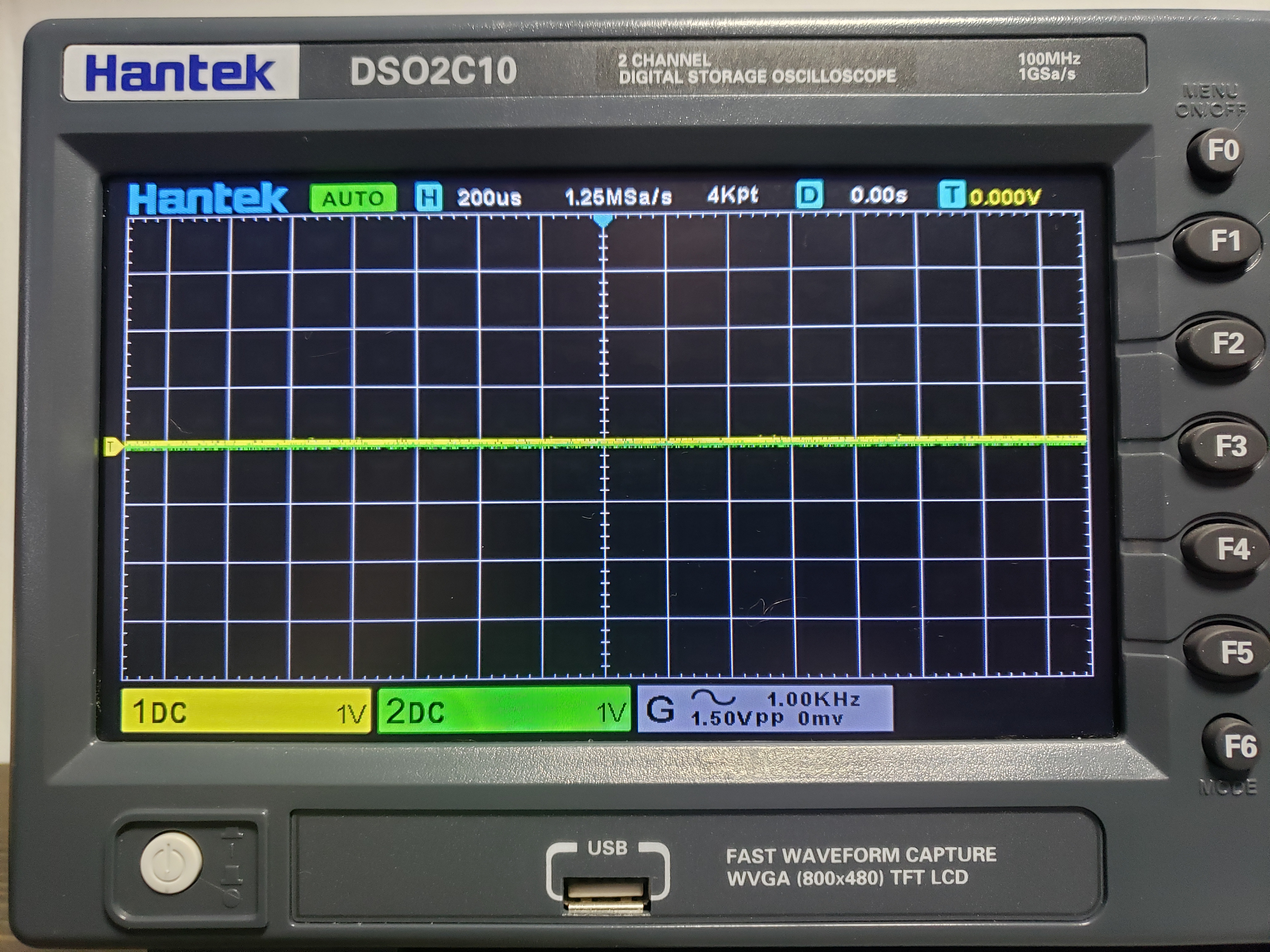
Set the generator settings to 1KHz and 600mVpp (You can try different voltages). Ignore the real output.
Set the channel to DC, 1x, 100mV/div (Adjust this to get best accuracy).
Note down the positive and negative peak voltages in mV.
Ex. 305 -312 for 305mV and -312mV
Create a file in the root of the USB drive named "cal_values" with this contents (Without spaces, Linux format!) :
REF=Generator Vpp
CAL_A=Vmax
CAL_B=Vmin
ex:
REF=600
CAL_A=305
CAL_B=-312
- Second pass: Ensure the file cal_values is placed in the root of the usb drive.
Run the package, it will read these values and perform the calibration,
generating the file "dds_calbration.dat", also updating to the eeprom.
Both steps will write the output to "log.txt", including the calibration values.Note we need to run dso3kb_calibrate_gen.upk first to reset any existing calibration, making sure there is no file cal_values on the USB. Again, make sure you run the backup builder before you get started so you have the option of restoring the original calibration data if you need to.
We'll need to connect the wave generator to channel one. Setting the wave gen to the specified settings and measure the peaks of the waveform. We add these to a file on the USB stick called cal_values. Mine looks like this:
REF=600
CAL_A=340
CAL_B=-348
This is placed in the same folder as dso3kb_calibrate_gen.upk. Everything is in mV. CAL_A is the positive peak and CAL_B is the negative. You can also change the reference voltage if you want to try it at different levels. Once this file is in place, we run dso3kb_calibrate_gen.upk again. The program writes a file log.txt to the USB with the results. After the scope reboots check the wave gen, and re-adjust if necessary.
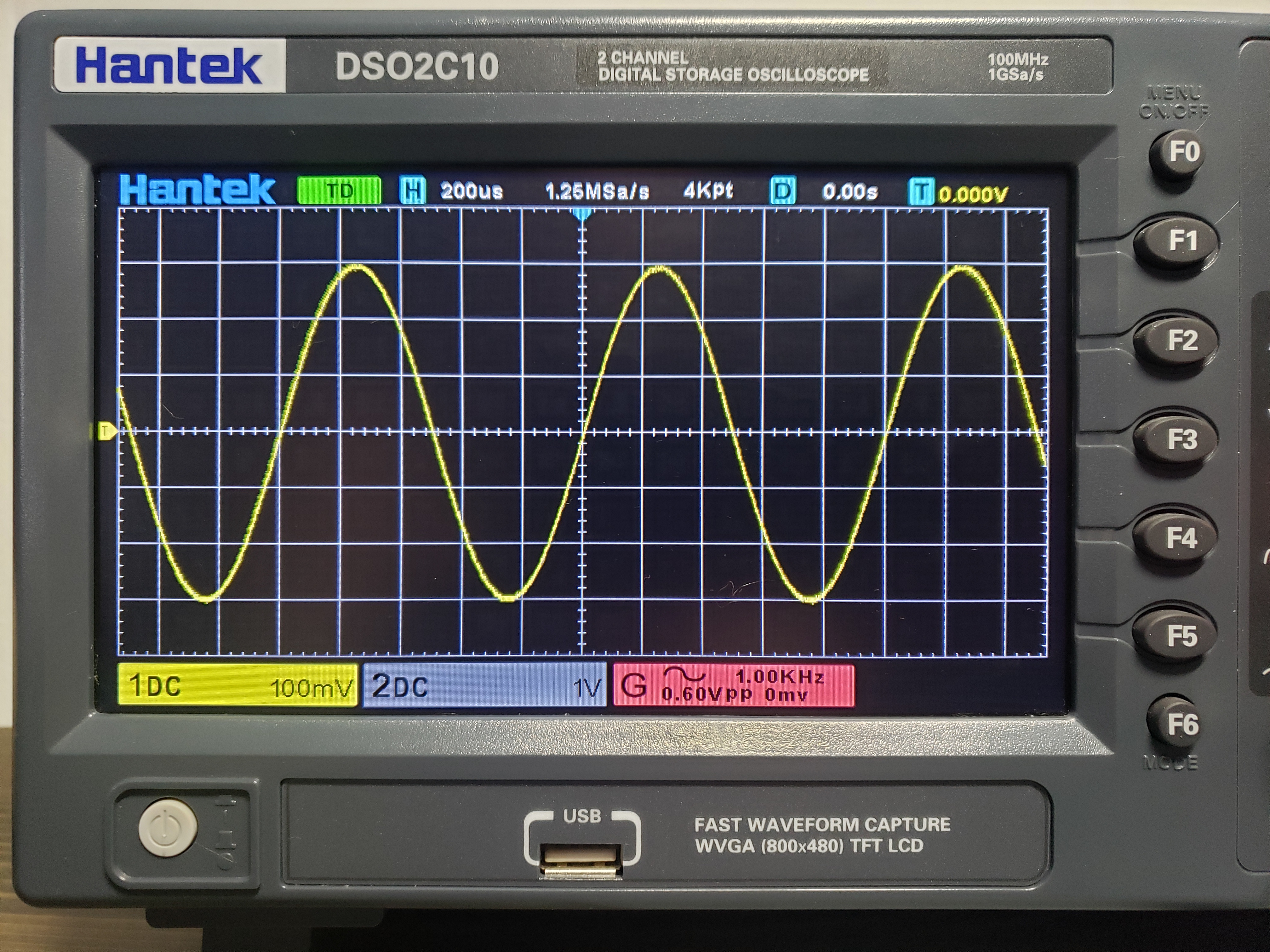
Hopefully you see something like this when it's all done.
References:
Hacking thread https://www.eevblog.com/forum/testgear/hacking-the-dso2x1x/
DavidAlfa's FAQ https://www.eevblog.com/forum/testgear/new-hantek-dso2x1x-models/msg3559217/#msg3559217
DavidAlfa's Google Drive https://drive.google.com/drive/folders/18hlxm84RwWpsml4CEz2QG75YZiT5vIMI
Files:
Backup Builder
2D15 Conversion
Generator Calibration
Datasheets:
HFD4 subminiature relay.
TE Axicom IM02 relay, alternative to HFD4
TI DAC902, 12 bit digital-to-analog converter
LMH6702 wideband op amp